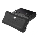
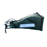
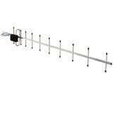
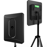
An FPV drone antenna amplifier should be selected based on the compatibility of the entire system, not the largest number listed in the specifications. Operating frequencies, output power, antenna gain, polarization, connectors, cable, power supply and communication mode must match the equipment used with the device.
Power measured in watts or dBm, antenna gain measured in dBi and active-stage gain measured in dB are different parameters. They are not interchangeable and cannot determine link quality or range without considering the other system components.
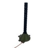
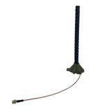
The term “antenna amplifier” may refer to several types of equipment: an active radio-frequency amplifier, a high-gain directional antenna or a complete remote antenna system combining both components. As a result, two visually similar products may have different operating principles, connection requirements and compatibility limitations.
This guide explains what W, dBm, dB and dBi mean, how to check frequency compatibility and why matching connectors alone do not confirm that the equipment will work together.
What Is an Antenna Amplifier?
Technically, an antenna and an active amplifier perform different functions. An antenna converts an electrical signal into an electromagnetic wave and vice versa. An amplifier operates within the RF path and increases the signal level in the transmit path, receive path or both, depending on its design.
Passive antenna
Does not require a separate power supply. Its primary parameters are frequency range, gain in dBi, radiation pattern, polarization, VSWR, impedance and connector type.
Active amplifier
Contains an electronic amplification stage and requires power. Selection criteria include operating frequencies, output power, gain, allowable input level and operating mode.
Remote antenna system
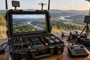
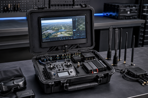
May include antennas, active modules, cables, adapters, a power supply and mounting hardware. Compatibility must be evaluated for the complete system rather than one component.
A passive directional antenna is sometimes marketed as a “signal booster” even though it contains no electronic amplifier. The specifications help identify the equipment type: dBi describes antenna gain, while output power in watts or dBm applies to an active transmission stage.
Understanding the Main Parameters
| Parameter | What it means | What to check |
|---|---|---|
| W or mW | The absolute power of an active RF stage. | Whether the figure describes output, power consumption, maximum or nominal power. |
| dBm | A logarithmic expression of absolute power relative to 1 mW. | Which point in the system the value refers to: input, output or received signal. |
| dBi | Antenna gain relative to a theoretical isotropic radiator. | The radiation pattern and frequency at which the stated gain is achieved. |
| dB | A relative measurement of gain or loss. | Whether the value applies to an amplifier, cable, adapter or another component. |
| MHz or GHz | The operating frequency range. | The exact lower and upper limits, not only the general band name. |
| VSWR | A measure of how well the antenna is matched to the RF path at a particular frequency. | The frequency range over which the manufacturer guarantees the stated matching performance. |
| Ω | The characteristic impedance of the RF path. | Matching impedance across the equipment, cable, antenna and adapters. |
| Polarization | The orientation of the electromagnetic wave’s electric field. | Linear or circular polarization and, for circular systems, RHCP or LHCP. |
Amplifier Power: What Watts and dBm Indicate
RF output power may be expressed in watts or dBm. For example, 1 W equals 30 dBm, while 10 W equals 40 dBm. These are two ways of expressing the same physical quantity, but neither can be directly compared with dBi.
The RF output power shown in a product specification must be distinguished from the electrical power drawn from a battery or power supply. A stated maximum value may also differ from the continuous operating rating. Accurate comparison requires the test conditions, allowable input level and nominal parameters for each frequency channel.
Higher power does not produce a proportional increase in range. The result also depends on receiver sensitivity, cable loss, antenna gain and directionality, interference, terrain, physical obstructions and proper component matching.
Transmit and receive performance must be evaluated separately. High transmitter output power does not improve receiver sensitivity by itself. A two-way link requires a balanced RF path compatible with the system’s transmit-and-receive switching mode.
What dBi Means for an FPV Antenna
The dBi value describes how strongly an antenna concentrates radiation in particular directions compared with a theoretical antenna that distributes energy equally in all directions. A passive antenna does not generate additional power; it changes the spatial distribution of the signal.
As dBi increases, the main lobe of the radiation pattern generally becomes narrower. The antenna may provide a higher signal level within its intended sector, but it also becomes more sensitive to the relative position of the equipment. The highest dBi rating is therefore not always the best option.
Directional and omnidirectional antennas
An omnidirectional antenna covers a wider area around its axis but concentrates less energy in one direction. Panel, Yagi and helical antennas produce more pronounced directional patterns. The appropriate design depends on the system architecture and required coverage sector, not solely on the stated gain.
Polarization
Antennas at both ends of the radio link should use matching polarization. Linear polarization requires consistent antenna orientation. Circular polarization also requires the correct rotation direction: RHCP and LHCP are not interchangeable. A polarization mismatch causes additional signal loss even when the frequency and connector type match.
Frequency Compatibility: Band Labels Are Not Enough
Labels such as 2.4G, 5.2G and 5.8G identify only a general frequency group. Compatibility must be checked against the exact operating range in MHz or GHz. Two devices marked “5 GHz” may support different parts of the spectrum and may not deliver their stated performance on the same channels.
The frequency limits should be checked for every element in the RF path:
- transmitter and receiver;
- active amplifier;
- antenna;
- cables, filters, splitters and adapters;
- other active components in the complete system.
A wideband antenna does not extend the operating range of a narrowband amplifier. Likewise, a tri-band label does not confirm support for every protocol or equipment model operating within those frequency bands.
Communication protocol and operating mode
Matching frequencies are not sufficient if an active device does not support the system’s operating mode. When transmission and reception alternate through a shared RF path, the amplifier must explicitly support the required bidirectional mode, switching speed and equipment configuration.
Any protocol or drone model listed in a product description should be confirmed for the specific amplifier version. Compatibility should not be assumed across different controller, receiver or antenna-module revisions simply because their names are similar.
Connectors, Cable and Impedance
FPV equipment and remote antenna systems may use SMA, RP-SMA, N-Type, QMA and other RF connectors. The connector family, body configuration, centre contact and connection side must all be checked. SMA and RP-SMA connectors may look similar but use different centre-contact configurations.
The characteristic impedance of all components should match. Many RF systems use 50-ohm components, but this must be confirmed in the equipment documentation rather than inferred from the connector’s appearance.
Coaxial cable introduces losses that depend on its type, length, operating frequency and connection quality. Attenuation generally increases with cable length and frequency. Antenna or amplifier specifications should therefore be evaluated together with the cable section of the system.
How Power, dBi and Losses Work Together
EIRP, or effective isotropic radiated power, is used to evaluate the radiated power of a system. In simplified form, it is calculated as follows:
EIRP (dBm) = output power (dBm) + antenna gain (dBi) − RF path losses (dB).
This relationship explains why systems cannot be compared by watts or dBi alone. Cables, adapters and other passive components reduce the resulting signal level.
EIRP does not describe the complete link quality. The radiation pattern, propagation loss, receiving-antenna gain, receiver sensitivity, bandwidth, noise level and link margin must also be considered. A stated range without corresponding test conditions cannot be treated as a universal specification.
Why Maximum Power Is Not Always Better
Excessive power does not correct a mismatch in frequency, polarization or connector type. It also cannot fully compensate for an unsuitable radiation pattern, substantial cable losses or insufficient receiver sensitivity.
When selecting an active antenna amplifier, check the following:
- Allowable input level: exceeding it may cause distortion or damage to the RF stage.
- Linearity: the amplifier must operate correctly with the intended signal type.
- Receive path: gain, noise characteristics and overload protection are all relevant.
- Power supply: voltage, current, connector type and operating time must match the documentation.
- Thermal conditions: operating limits cannot be determined from the enclosure material alone.
- Permitted EIRP: output power must be evaluated together with antenna gain and RF path losses.
How to Check Compatibility Before Selection
Amplifier compatibility with an FPV system should be checked in a logical order. If one of the fundamental parameters does not match, comparing power and dBi values is unnecessary.
- Record the exact equipment models. Identify the transmitter, receiver, controller, video system and antenna-module versions.
- Separate the communication links. The control and video links may use different frequencies and require separate components.
- Compare the exact frequency limits. The amplifier, antenna and connected equipment must cover the actual operating frequencies.
- Check the protocol and operating mode. An active device requires explicit confirmation of compatibility with the system’s transmit-and-receive method.
- Compare connectors and impedance. Check the connector family, centre contact, connection side, impedance and any required adapters.
- Verify polarization. Account for linear orientation or the RHCP or LHCP direction of circular polarization.
- Evaluate the cable section. Identify the cable type and length, loss at the operating frequency and number of connections.
- Check the power supply and package contents. Confirm whether cables, adapters, mounting hardware, a battery or a charger are included.
If the manufacturer does not provide exact frequency limits, input and output parameters or a list of compatible equipment, request technical confirmation instead of relying on the marketing name.
Common Selection Mistakes
- Comparing W with dBi. Watts describe the power of an active device, while dBi describes the directional gain of an antenna.
- Using only the band name. A 5G or 5.8G label does not replace the exact frequency limits.
- Treating a matching connector as proof of compatibility. The centre contact, impedance, frequencies and permitted power must also match.
- Ignoring cable losses. A long cable run or multiple adapters can significantly affect overall RF performance.
- Mixing polarization types. Incorrect linear orientation or an RHCP and LHCP mismatch introduces additional losses.
- Expecting a guaranteed range. Actual distance depends on the complete RF link and signal-propagation conditions.
- Selecting one component without checking the complete kit. Compatible cables, power components, mounts or adapters may also be required.
Where to View Compatible Equipment
The SKYHUB catalogue includes separate sections for active antennas and signal amplifiers and antennas for FPV drones and compatible systems. Before selecting a product, check the specifications of the exact model, including frequency range, power, dBi, polarization, connectors, power requirements and package contents.
Information to Prepare for a Consultation
To verify compatibility, provide the exact models of the drone, controller, transmitter and receiver, along with their operating frequencies, connector types, antenna polarization and the components already included in the system. If the markings are unclear, provide legible photographs of the connectors and equipment labels.
Specialized radio equipment must be purchased and used lawfully, for its intended purpose and in compliance with current restrictions. Frequencies and permitted operating conditions should be checked against the Law of Ukraine “On Electronic Communications” and the current Frequency Allocation and Use Plan of Ukraine. Complex system selection and connection should be handled by a qualified specialist.
FAQ: FPV Antenna Amplifiers
What is the difference between an antenna amplifier and a high-gain antenna?
An active amplifier requires power and increases the RF signal level within its specified operating range. A high-gain antenna passively redistributes energy in particular directions and does not generate additional power.
Does a higher dBi rating always provide a better link?
No. A higher dBi value is generally associated with a narrower radiation pattern, so performance depends on the required coverage sector, frequency, polarization and relative position of the antennas.
Will a 5.8 GHz amplifier work with a 5.2 GHz system?
Only if the amplifier documentation explicitly states an operating range that covers the system’s actual frequencies. A “5 GHz” label or a similar connector does not confirm compatibility.
How can I check whether an amplifier is compatible with an FPV system?
Compare the exact equipment models, frequency limits, protocol and communication mode, allowable input levels, connectors, impedance, polarization, power requirements and cable specifications. A band name or drone model in the product title is not sufficient.
Does an antenna amplifier guarantee a longer range?
No. Actual performance depends on the complete RF link budget, antennas, cable, receiver sensitivity, interference, noise level and signal-propagation conditions.