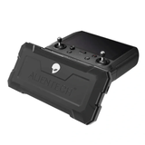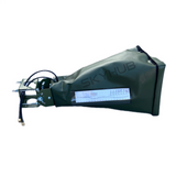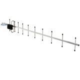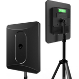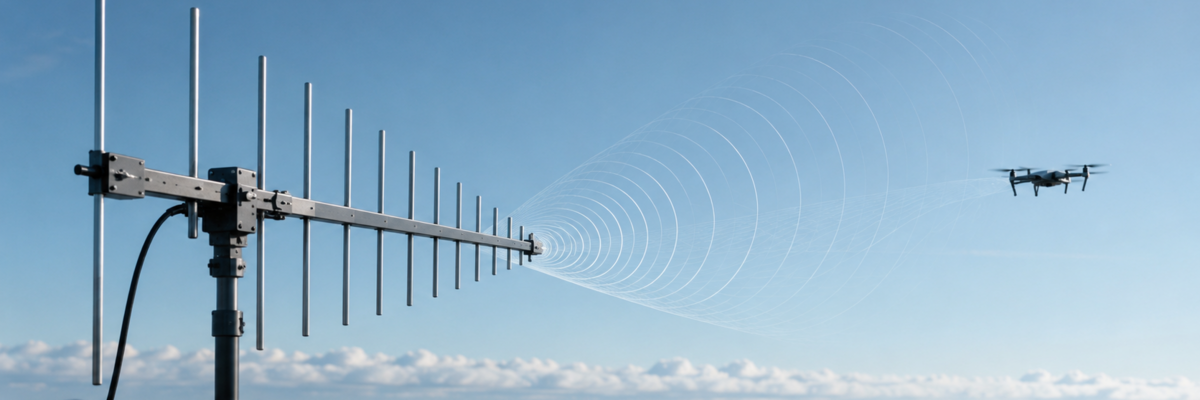
A log-periodic antenna is a broadband directional antenna consisting of a series of elements of different sizes. Different groups of these elements become most active at different frequencies, allowing one antenna to maintain useful operating characteristics across a much wider frequency range than many resonant antennas.
For UAV systems, this type of antenna can be useful on the ground side of a radio link when directional coverage and operation across a broad frequency range are required. However, the term “log-periodic” alone does not guarantee compatibility: the frequency range, polarization, gain, radiation pattern, connector type, and other parameters of a specific model must be checked separately.
What Is a Log-Periodic Antenna?
The most common version of this design is the log-periodic dipole array, or LPDA. It consists of several parallel dipole elements arranged from shorter elements at one end to longer elements at the other. The spacing between adjacent elements also changes progressively.
The dimensions and relative positions of the elements follow a defined scaling ratio. This geometrical repetition at different scales is what gives the antenna its “log-periodic” name: its electrical characteristics vary periodically with the logarithm of frequency.
The practical advantage of this principle is a wide operating bandwidth. Instead of relying on a single resonant element designed mainly for a narrow frequency range, an LPDA uses multiple elements of different lengths. As frequency changes, the active region of the antenna shifts along the array.
Wide Bandwidth
Elements of different lengths allow the antenna to operate across different parts of its specified frequency range without mechanical retuning.
Directional Pattern
Most of the receive or transmit sensitivity is concentrated in a defined direction rather than distributed evenly around the antenna.
Active Region
At a given frequency, the greatest contribution comes not from the entire array at once, but from a group of elements whose electrical dimensions are close to the operating wavelength.
How a Log-Periodic Antenna Works
To understand how an LPDA works, imagine a sequence of dipoles with different lengths. For each operating frequency, there is a region of the array whose elements have electrical dimensions that are best suited for interacting with the signal. This part is known as the active region.
As frequency increases, the active region shifts toward the shorter elements. As frequency decreases, it moves toward the longer ones. This means the antenna does not depend on a single resonant element.
In a typical log-periodic dipole array, adjacent elements are connected to the feed line with alternating polarity. Together with the selected spacing between dipoles, this creates the required phase relationship between signals in the active section of the array and forms a directional radiation pattern.
Elements located far from the active region make a much smaller contribution to radiation. In simplified terms, longer elements behind the active section may influence the field in a way similar to a reflector, while shorter elements in front may behave somewhat like directors in a directional antenna system.
Key characteristic: log-periodic behavior is created not by one specific dipole length, but by the scaled geometry of the entire antenna. This is why an LPDA is primarily considered a broadband directional antenna.
Radiation Pattern of a Log-Periodic Antenna
A radiation pattern shows how effectively an antenna receives or transmits signals in different directions. A conventional LPDA typically has a pronounced main lobe directed along the longitudinal axis of the array, toward the shorter elements.
This is a fundamental difference from omnidirectional antennas, which are designed to provide broad coverage around the antenna in the horizontal plane. A log-periodic antenna concentrates more of its directional response within a defined sector.
Main Radiation Pattern Characteristics
- Main lobe. The direction in which the antenna has its highest sensitivity or radiation intensity.
- Beamwidth. Indicates how wide the antenna’s primary operating sector is.
- Back radiation. Some energy may be transmitted or received from the opposite direction, but its level is typically lower than in the main direction.
- Side lobes. Additional directions of sensitivity whose characteristics depend on the specific antenna design.
- Front-to-back ratio. Describes the difference between signal levels in the main and opposite directions.
One reason LPDAs are used in measurement and radio engineering applications is that their radiation pattern and input characteristics can remain relatively stable over a wide frequency range. This does not mean that all parameters remain absolutely identical throughout the full bandwidth: actual gain, beamwidth, VSWR, and other characteristics should be checked in the documentation for the specific antenna.
What Polarization Does an LPDA Use?
A conventional log-periodic dipole antenna uses linear polarization. Its orientation is determined by the position of the dipole elements. If the receiving and transmitting antennas use different polarizations, additional signal loss occurs.
For this reason, when evaluating an antenna for a UAV communication system, checking the frequency range alone is not enough. Polarization must also match the other side of the radio link.
Log-Periodic vs Yagi vs Omnidirectional Antenna
An LPDA is sometimes confused with a Yagi-Uda antenna because both designs use a row of transverse elements and can have directional radiation patterns. However, their operating principles and typical bandwidths are different.
| Parameter | Log-Periodic Antenna | Yagi-Uda Antenna | Omnidirectional Antenna |
|---|---|---|---|
| Typical characteristic | Broadband operation using elements of different scales | Operation around a defined frequency range using a driven element, directors, and a reflector | Broad azimuth coverage around the antenna |
| Directionality | Directional | Directional | Primarily omnidirectional in the horizontal plane |
| Operating bandwidth | Usually wide | Usually narrower, although it depends on the specific design | Depends on antenna type and design |
| When to consider it | When both broadband operation and a directional pattern are required | When the system operates in a defined range and directional coverage is required | When spatial coverage is more important than concentrating the signal in one direction |
There is no universally “best” antenna type without knowing the parameters of the radio system. An LPDA is particularly useful when wide bandwidth is required together with a directional radiation pattern. If the system operates in a narrow range or requires a different coverage pattern, another antenna type may be more appropriate.
Using Log-Periodic Antennas for UAV Systems
In UAV systems, a log-periodic antenna is primarily worth considering as part of the ground-side radio system when its specifications match the relevant communication link. A directional design is used where a defined sector is the priority, while broad operating bandwidth allows compatible equipment to operate within the frequency range specified by the manufacturer.
Depending on the specifications of the particular antenna and radio equipment, an LPDA may be used for receiving or transmitting signals, telemetry systems, video links, ground stations, radio monitoring, and radio-environment measurements. Compatibility must be verified separately for each application.
Why Wide Bandwidth Can Be Useful
If a radio system or measurement setup needs to operate across a broad frequency range, using a separate narrowband antenna for every part of the spectrum can be inconvenient. A log-periodic design can cover a wide range with one antenna, provided that the required frequencies are fully within its specified operating band.
Wide bandwidth does not mean identical performance at every frequency. For a real system, VSWR, gain, and radiation pattern curves should be evaluated specifically within the required part of the operating range.
What Actually Determines Radio Link Performance
A common mistake is to evaluate an antenna only by its gain in dBi. Gain is important, but it describes only one characteristic of an antenna system. Overall radio link performance depends on a combination of parameters.
- Operating frequency. The antenna must cover the required frequency range according to the manufacturer’s documentation.
- Radiation pattern. A narrow beam and a wide sector serve different purposes.
- Polarization. It should match the polarization used on the other side of the radio link.
- Antenna gain. It should be evaluated at the required frequency rather than only by the maximum value listed in specifications.
- VSWR and impedance matching. These affect losses when transferring RF energy between the radio equipment and antenna.
- Cable and connector losses. Cable length, cable type, connector quality, and adapters all influence the total system performance.
- Radio equipment specifications. Transmitter power, receiver sensitivity, and other characteristics are independent of the antenna and must be assessed separately.
A log-periodic antenna is not a universal “range booster.” It creates a particular radiation pattern and operates within a specified frequency range, but the final characteristics of the radio link depend on the complete system and signal propagation conditions.
How to Choose a Log-Periodic Antenna for a UAV System
The correct selection process starts with the technical specifications of the equipment to which the antenna will be connected, not with maximum dBi or antenna size. Several parameters should be checked in sequence during the initial evaluation.
- Identify the required operating frequency range. It must fit completely within the antenna’s specified bandwidth.
- Check the required radiation pattern. Consider not only gain but also main-lobe beamwidth and front-to-back ratio.
- Verify polarization. LPDAs most commonly use linear polarization, but the specifications of the particular model remain decisive.
- Check impedance and VSWR. The antenna must be properly matched to the RF path within the required frequency range.
- Confirm the connector type. The presence of a physically similar connector does not by itself confirm full electrical compatibility.
- Check maximum permissible power. This is essential when the antenna is used for transmission.
- Evaluate mechanical and environmental specifications. Mounting method, weight, environmental protection, and allowable temperature range should match the intended operating conditions.
In the SKYHUB drone antenna section, you can compare available antenna solutions and their stated specifications. Parameters from one model should not be assumed to apply to another: operating frequency, gain, connectors, and compatibility must be verified using the specific product page or technical documentation.
Does a Log-Periodic Antenna Need an Amplifier?
An LPDA and an antenna amplifier perform different functions. The antenna determines, among other things, the frequency and spatial characteristics of signal reception or transmission. An amplifier is a separate active component of the RF chain.
Adding an active component does not correct an unsuitable antenna frequency range, polarization mismatch, significant impedance mismatch, or an inappropriate radiation pattern. Amplifier compatibility also depends on its own operating range, permitted signal levels, power requirements, and connection configuration.
For this reason, antenna amplifiers should be considered as a separate category of equipment rather than a mandatory component of every log-periodic antenna system.
Common Mistakes When Evaluating an LPDA
- Assuming every long antenna array is log-periodic. Visual similarity to a Yagi or another directional antenna does not define the actual design principle.
- Focusing only on maximum dBi. This value alone says nothing about frequency or polarization compatibility.
- Ignoring beamwidth. Two antennas with similar gain can have very different spatial coverage patterns.
- Assuming the entire stated bandwidth performs identically. Real antenna characteristics vary with frequency even within the specified operating range.
- Ignoring cable losses. Losses in the feed line and connectors are part of the total radio link budget.
- Expecting guaranteed range from an antenna replacement alone. Range depends on the entire radio system, terrain, obstructions, RF environment, and propagation conditions.
Log-Periodic Antennas in Specialized Radio Systems
Broadband directional antennas are used beyond UAV communications. They are also found in radio monitoring, laboratory and EMC measurements, signal direction-finding systems, broadband reception, and other radio engineering applications.
A separate group includes antennas intended for specialized equipment. SKYHUB has a dedicated category for antennas for military systems and electronic warfare equipment. A wide operating frequency range alone does not make a specific antenna suitable for such equipment: compliance with the technical requirements, permissible power, radiation pattern, impedance matching, and other system parameters must also be confirmed.
Usage note. Radio transmission and specialized equipment should be used only for its intended purpose and in accordance with applicable Ukrainian legislation and radio-frequency spectrum regulations. Electronic warfare and other specialized systems require professional selection with consideration of both legal and technical restrictions.
What to Check Before Choosing an Antenna
If a log-periodic antenna is being considered for a ground station, communication system, or other equipment, it is useful to prepare the relevant technical information before requesting advice. At a minimum, this includes the operating frequency range, equipment type, required polarization, connector specifications, and radiation-pattern requirements.
You should also know whether the antenna will be used only for reception or for both transmission and reception. In the latter case, maximum permissible power, VSWR, and impedance matching with the transmitter path become particularly important.
If the exact radio system specifications are unavailable, the equipment documentation should be found first. Choosing an antenna only by its appearance, UAV name, or stated gain creates a significant risk of incompatibility.
When selecting an antenna solution, you can compare the specifications of models available in the SKYHUB catalog and clarify their compatibility with specific equipment. For an accurate assessment, it is useful to know the frequency range, radio system type, polarization, connector, and radiation-pattern requirements.
Available options can be found in the drone antenna category.
FAQ: Frequently Asked Questions About Log-Periodic Antennas
What is a log-periodic antenna?
A log-periodic antenna is a broadband antenna with elements of different sizes whose geometry changes according to a constant scaling ratio. In a common LPDA design, different sections of the dipole array become active at different frequencies.
Which direction does a log-periodic antenna point?
In a conventional log-periodic dipole array, the main lobe is directed along the antenna axis toward the shorter elements. The exact beamwidth and the levels of side and back lobes depend on the specific design.
What is the difference between a log-periodic antenna and a Yagi antenna?
Both antennas can be directional, but an LPDA is generally designed for a much wider operating bandwidth using scaled elements of different lengths. A Yagi-Uda antenna uses a different construction principle and typically operates over a narrower frequency range.
Is a log-periodic antenna suitable for UAV systems?
Yes, a log-periodic antenna can be used in compatible ground-based UAV communication, telemetry, video reception, or radio-monitoring systems. The operating frequency range, polarization, gain, radiation pattern, connector, and other parameters of the specific radio system must be verified.